BuzzBall 3.0
EAA Founders Innovation Prize Entry
Ethan Brodsky
2019
Executive Summary
This submission builds upon the BuzzBall concept of the two previous years. The innovation aids the pilot in maintaining or restoring controlled flight through haptic (touch/vibration) feedback applied provided through the pilot’s seat cushion. This report details minor improvements and additional flight testing made since last year.
Background
Spins subsequent to aerodynamic stalls are a major cause of fatal loss-of-control accidents. While most aircraft have predictable behavior when stalled in coordinated flight, uncoordinated stalls with the “ball out of center” are not necessarily so forgiving, and the resultant loss of roll control can lead to immediate and severe roll excursions, unexpectedly putting the aircraft in an extreme bank angle from which recovery may be difficult or impossible. This is especially dangerous when it occurs at low altitude. For example, a pilot attempting to tighten an overshooting base-to-final turn by using bottom rudder to skid the aircraft, while already imposing maneuvering loads in a steep turn, leading to an accelerated stall and a drop of the already-low wing and out-of-control impact with the ground, is a classic and too-often repeated occurrence in the NTSB accident database. While all low-altitude stalls are dangerous, recovery from a coordinated stall without an associated loss of roll control is far more likely.
It is well understood in aviation that this stall-spin scenario can be avoided by maintaining coordinated flight. While aviators since the beginning of flight have been reminded that they must use the rudder to do this, especially during slow flight, the high prevalence of stall‑spin accidents among pilots of all experience levels after nearly 100 years of flight suggests that “keeping the ball centered” can be a challenging task.
Definition of Coordinated Flight
“Coordinated flight” is defined as flight without sideslip, or “sideways motion” that is not aligned with the relative wind in the vertical axis. Mathematically, it is a state in which the aircraft sideslip angle, or “directional angle of attack” (typically represented as β in flight dynamics equations) is zero. In addition to the improved behavior in stalls, zero sideslip angle is desirable because it minimizes drag and is more comfortable for passengers.
It is nontrivial to measure sideslip angle. In flight testing, it is typically measured using a vane‑type transducer or a five-hole pressure probe, but such systems are not typically installed on small general aviation aircraft. Instead, lateral acceleration is used as a surrogate for sideslip angle. When an aircraft is flown in a slip, aerodynamic forces on “side of the aircraft” traveling into the relative wind will create an acceleration that is not aligned with the orthogonal aircraft axes. Zero lateral acceleration indicates zero sideslip (assuming there are no other external forces not aligned with the aircraft axes, such as thrust asymmetry in a twin-engine aircraft), and non-zero lateral acceleration is related to sideslip in a non-linear manner that is based also on airspeed and aircraft weight.
Coordination is typically indicated using a “turn coordinator” or “turn and slip indicator” instrument, which includes a curved bubble level-style inclinometer (in some pusher or twin-engine aircraft a yaw string is used instead). These instruments provide a simple visual representation of coordinated flight, with a scale that relates to the lateral acceleration perceived by aircraft occupants. The inclinometer is typically marked with two vertical lines, sometimes called the “cage”, that mark the central position of the ball in coordinated flight and allow quantification of how “far out” from center the ball is.
Motivation
It is difficult for many pilots to consistently connect the intellectual knowledge that maintaining coordination is important to safe flight with the physical sensory and motor processes required to do so. While many experienced pilots (especially those who fly taildraggers, gliders, or other aircraft with high adverse yaw moments) have developed a “seat of the pants” feel for required rudder inputs, many pilots never develop this intuitive sense, and they must constantly remind themselves to check the coordination instrument and adjust their rudder pedal forces accordingly, a task that is often forgotten during high-workload stages of flight. The fact that coordination can only be checked in this manner visually imposes another task on the visual sensory system, which is often already task-saturated. This is especially true for VFR pilots who tend to be more accustomed to looking outside and have not developed a good instrument scan.
Pilots maneuvering visually at low altitude (e.g. for a pattern and landing) must only monitor two instruments to maintain controlled flight – the airspeed indicator and the turn coordinator (perhaps this is why the conventional six-pack panel layout places those two instruments in a vertical column). Eliminating the need to look at the turn coordinator would halve the number of instruments that the pilot must look at, and in an aircraft equipped with a glareshield-mounted or heads-up style AoA indicator or auditory/vibratory pre-stall warning system, the pilot would be able to keep his or her attention focused entirely outside.
The focus of this work is to eliminate the need for a pilot to visually check a coordination instrument by adding a system that gives coordination feedback using haptic/tactile (touch) presentation. While a pilot’s visual sensory system is highly loaded during flight, the pilot’s somatosensory system is very much underutilized. The somatosensory system includes the senses of touch, balance, warmth, pain, and body and joint position and strain (proprioception). The “sense of touch” itself includes a number of different sensations; our bodies are capable of sensing mechanical pressure, displacement of tissue, and vibration.
It seems intuitively reasonable to present coordination indications to the somatosensory system, as it is the system that should be sensing coordination by perceiving lateral acceleration or forces transmitted to the body through the seat (much as the body can sense the G loads in a highly loaded turn).
Overview
For the purposes of the EAA’ Founder’s Innovation Prize competition evaluation criteria, the Solution is the “Buzz Ball” system described below. The Condition is uncoordinated flight and the Solution addresses this condition by providing a means of increasing a pilot’s ability to recognize and correct the condition, reducing the incidence of loss of control due to uncoordinated stalls and thus save lives.
 The
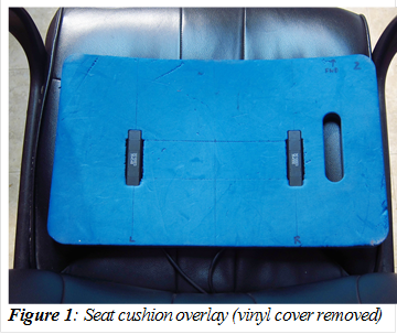
system consists of two physical parts. The pilot‑facing portion is very
simple and consists of a thin seat cushion overlay with two small embedded
vibrating actuators, positioned such that one is centered under each of the
pilot’s buttocks. The internals of the seat overlay are shown in Figure 1
– to improve appearance and comfort, the overlay is wrapped in a vinyl cover.
The
system consists of two physical parts. The pilot‑facing portion is very
simple and consists of a thin seat cushion overlay with two small embedded
vibrating actuators, positioned such that one is centered under each of the
pilot’s buttocks. The internals of the seat overlay are shown in Figure 1
– to improve appearance and comfort, the overlay is wrapped in a vinyl cover.
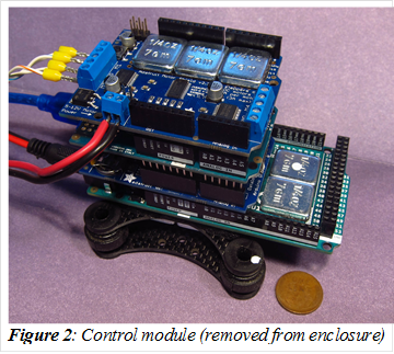 The
second part of the system is the control unit, shown in Figure 2. This
box is mounted to a roughly horizontal surface in the aircraft, in this case to
the floor of the baggage area. Inside this box is a small computer, about the
size of three decks of playing cards. It consists of five stacked circuit
boards – an Arduino-based computer board, two separate board with an inertial
measurement units (IMUs), a motor drive board, and a data-logging board with a
Secure Digital (SD) memory card. A single cable connects the two modules, and
power is supplied from a 12V “cigarette lighter” plug on the aircraft’s panel.
The
second part of the system is the control unit, shown in Figure 2. This
box is mounted to a roughly horizontal surface in the aircraft, in this case to
the floor of the baggage area. Inside this box is a small computer, about the
size of three decks of playing cards. It consists of five stacked circuit
boards – an Arduino-based computer board, two separate board with an inertial
measurement units (IMUs), a motor drive board, and a data-logging board with a
Secure Digital (SD) memory card. A single cable connects the two modules, and
power is supplied from a 12V “cigarette lighter” plug on the aircraft’s panel.
During coordinated flight, the system is idle; when the ball moves out of center, the actuator on that side vibrates. Instead of having to remember to look at a gauge and then “step on the ball”, the pilot will be alerted of the uncoordinated flight condition and can simply “step on the buzzing ball” to correct it. The system also detects when the aircraft is in a spin and provides spin recovery feedback instructing rudder opposite the direction of spin.
The system was tested in my aircraft, a 1981 Wag-Aero Wag-a-Bond Traveler, which is an experimental amateur-built replica inspired by the Piper Vagabond. Informed consent was obtained from all participants.
Hardware
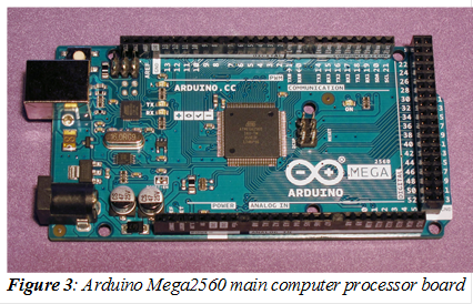 The
control computer is an Arduino Mega2560 R3 (Figure 3). It is based on the
AVR ATmega2560, an 8-bit 16 MHz microcontroller with 256 KB of flash and 8
KB of RAM, and many channels of analog and digital input and output (IO). The
board has 54 digital IO pins and 16 analog IO pins, though only a tiny fraction
of these are used in this project.
The
control computer is an Arduino Mega2560 R3 (Figure 3). It is based on the
AVR ATmega2560, an 8-bit 16 MHz microcontroller with 256 KB of flash and 8
KB of RAM, and many channels of analog and digital input and output (IO). The
board has 54 digital IO pins and 16 analog IO pins, though only a tiny fraction
of these are used in this project.
It is programmed by a laptop connected via a USB cable, and the Arduino developer community provides a free open-source development environment (Arudino IDE, from arudino.cc) that allows quick and easy development and deployment of code onto the hardware. The board has pin headers that allow “shield” boards to be stacked on top of it.
The Arduino Mega2560 is an upgrade from the Arduino UNO used the first year. The change was initially made due to conflicts in pin assignments between the motor control and datalogging boards, as each of these boards used pins D11 and D12 for different purposes. However, after the motor control board was later changed to an improved unit, eliminating this conflict, the Mega2560 board was retained, as it has more memory, reducing constraints on how much extraneous debugging code could be included. If physical space was at a premium, then moving back to the UNO-based platform would be simple.
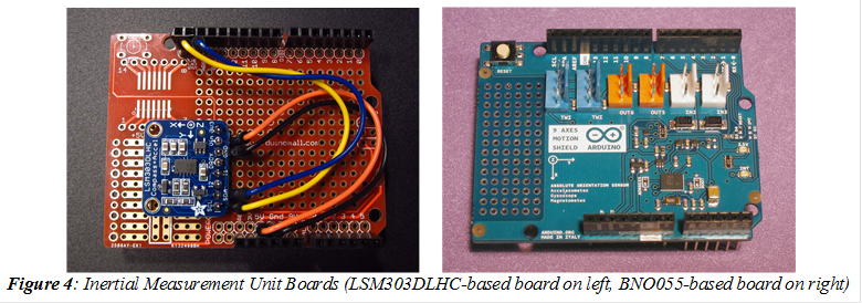 Stacked
on top of the control computer board is a pair of sensing boards, shown in
Figure 4. One board is the same as was used in the version presented in 2017 -
a prototyping shield with an Adafruit 1120 triple-axis 16-bit accelerometer/magnetometer
board based on the STMicroelectronics LSM303DLHC sensor. The board is
arbitrarily mounted such that the +X axis is aft in the aircraft, +Y is right,
and +Z is up, and the sensor is configured to its ±2g “nominal” gain, which
should work up accelerations of around 3g (for aerobatic aircraft that may
experience higher forces, it can be configured with a different gain setting,
allowing accurate measurement of forces far in excess of those survivable by
humans). The sensor chip communicates using the I²C serial communication
protocol, which is natively supported on the Arduino platform.
Stacked
on top of the control computer board is a pair of sensing boards, shown in
Figure 4. One board is the same as was used in the version presented in 2017 -
a prototyping shield with an Adafruit 1120 triple-axis 16-bit accelerometer/magnetometer
board based on the STMicroelectronics LSM303DLHC sensor. The board is
arbitrarily mounted such that the +X axis is aft in the aircraft, +Y is right,
and +Z is up, and the sensor is configured to its ±2g “nominal” gain, which
should work up accelerations of around 3g (for aerobatic aircraft that may
experience higher forces, it can be configured with a different gain setting,
allowing accurate measurement of forces far in excess of those survivable by
humans). The sensor chip communicates using the I²C serial communication
protocol, which is natively supported on the Arduino platform.
The second board is an Arduino 9-Axis Motion Shield (A000070), which was used in the version submitted in 2018. This board contains a Bosch BNO055 absolute orientation sensor, which includes a three-axis 14-bit accelerometer, a three-axis 16-bit solid-state gyroscope, a three-axis geomagnetic sensor, and a 32-bit microcontroller running the Bosch BSX3.0 FusionLib software. The unit communicates over the I2C serial protocol, which is natively supported on the Arduino platform, and can be trivially queried to get either raw measurements (acceleration, rotation, and magnetic field orientation) or derived measurements like the “absolute orientation” of the board (either with Euler angles defining heading/pitch/yaw or a rotation quaternion). It is also configured in its ±2g “nominal” range but could easily be configured for higher (or designed to auto-switch upon overflow)
The board is oriented in the manner most convenient for mounting (in the Arduino stack with the wires exiting to the rear), then the unit’s “axis remapping” functionality was used to define the axes such that a +X acceleration value corresponds to the aircraft accelerating forward, +Y accelerating to the left, and +Z accelerating up (thus gravity yields a +Z acceleration when the aircraft is flying straight and level). For rotation angles, heading is magnetic, positive roll is a bank to the right, and positive pitch is “nose up”.
 The reason for
installing both boards is that the BNO055-based board used in 2018 proved to be
less suitable for providing the acceleration measurements required for
calculating ball position than the LSM303DLHC-based board used in 2017. Raw
acceleration measurements could not be sampled as quickly and the built-in
low-pass filters did not perform as well as the software-based filters used
previously. Furthermore, it took some time to initialize and calibrate itself each
time power was applied, whereas the other sensor allowed immediate sampling of
the acceleration data. The BNO055 sensor is essential for providing the
rotational rate information for the “spin mode”, and extremely useful in providing
information to help understand the datalogs, but the LSM303DLHC-based sensing
solution has been more effective for the core functionality of the unit.
The reason for
installing both boards is that the BNO055-based board used in 2018 proved to be
less suitable for providing the acceleration measurements required for
calculating ball position than the LSM303DLHC-based board used in 2017. Raw
acceleration measurements could not be sampled as quickly and the built-in
low-pass filters did not perform as well as the software-based filters used
previously. Furthermore, it took some time to initialize and calibrate itself each
time power was applied, whereas the other sensor allowed immediate sampling of
the acceleration data. The BNO055 sensor is essential for providing the
rotational rate information for the “spin mode”, and extremely useful in providing
information to help understand the datalogs, but the LSM303DLHC-based sensing
solution has been more effective for the core functionality of the unit.
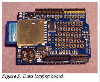
 Next in the stack is an
Adafruit 1141 data-logging shield for Arduino (Figure 5). This unit has a slot
for an SD card and a built-in battery-backed real-time-clock (RTC). This
addition made data-logging to an SD card nearly as simple as datalogging to a
laptop over a serial port (the solution that was awkwardly used last year),
with files time-stamped with the actual date and time, reducing requirements
for manual record-keeping and (which can be distracting during in-flight
testing) and simplifying later analysis.
Next in the stack is an
Adafruit 1141 data-logging shield for Arduino (Figure 5). This unit has a slot
for an SD card and a built-in battery-backed real-time-clock (RTC). This
addition made data-logging to an SD card nearly as simple as datalogging to a
laptop over a serial port (the solution that was awkwardly used last year),
with files time-stamped with the actual date and time, reducing requirements
for manual record-keeping and (which can be distracting during in-flight
testing) and simplifying later analysis.
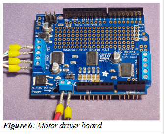
On top of the stack is the motor control board, an Adafruit 1438 v2.3 Motor/Stepper/Servo shield, shown in Figure 6. This board uses a Toshiba TB6612 MOSFET quadruple half-H driver to provide four channels of DC motor control (or two channels of servo or stepper motors, functionality we do not use), with voltages up to 15V, and currents up to 1.2 A continuous and 3.2 A peak per channel. It contains a built-in PWM driver, allowing it to vary the motor speed with minimal CPU involvement. The motor control board is also controlled using the I2C serial communication protocol. This board is a major improvement over the old “Adafruit v1 clone” motor control shield used last year, which posed conflicts with other hardware due to the large number of digital IO pins it used.
The motor control unit is connected to the seat overlay unit with a four-conductor shielded cable. Bootlace ferrules were crimped onto each conductor to secure into the screw terminals of the motor control board. Two vibrating indicators were fit into slots cut in a foam “knee cushion”, which served as an excellent seat overlay. The optimal positioning was found to be 9” apart, positioned fore/aft such that they were under the pilot’s outer thighs. They are slightly less perceptible there than they are when in the original configuration centered under each buttock, but the wider spacing makes it easier to unconsciously distinguish which indicator is vibrating. The foam seat overlay was covered with marine vinyl to provide a finished appearance.
Vibrating actuators
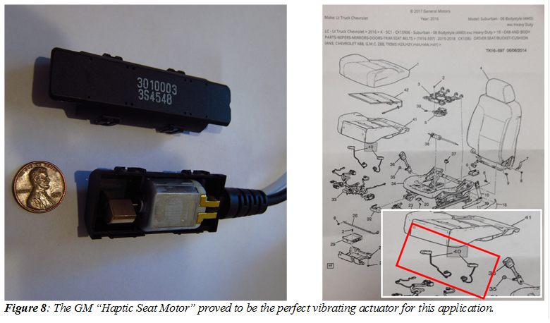 One
of the major challenges in this project was finding suitable vibrating actuator
to provide tactile feedback through the buttocks, which have proven to be
fairly insensitive to touch with the body’s weight compressing them against a
cushioned seat. After several failed attempts using vibrating actuators intended
for use in pagers, video game controllers, and motors with home-made eccentric
weights, all detailed in the 2018 report, the vibrating actuator intended for a
similar operator-alert application (Figure 8) was selected. The General Motors 84017512 “Haptic Seat Motor”
is one component of a “Lane Departure Warning System”, part of the “Driver
Alert Package” available as an option in a number of vehicles, including the
2017 Chevrolet Silverado. List price for the motors is $63.40 each and they
are widely available online or from dealerships for ~$40. These motors require
12V, pull approximately 100 mA each, and are extremely easy to feel when
installed in a seat cushion, as would be expected, considering that this is exactly
the application they are designed for.
One
of the major challenges in this project was finding suitable vibrating actuator
to provide tactile feedback through the buttocks, which have proven to be
fairly insensitive to touch with the body’s weight compressing them against a
cushioned seat. After several failed attempts using vibrating actuators intended
for use in pagers, video game controllers, and motors with home-made eccentric
weights, all detailed in the 2018 report, the vibrating actuator intended for a
similar operator-alert application (Figure 8) was selected. The General Motors 84017512 “Haptic Seat Motor”
is one component of a “Lane Departure Warning System”, part of the “Driver
Alert Package” available as an option in a number of vehicles, including the
2017 Chevrolet Silverado. List price for the motors is $63.40 each and they
are widely available online or from dealerships for ~$40. These motors require
12V, pull approximately 100 mA each, and are extremely easy to feel when
installed in a seat cushion, as would be expected, considering that this is exactly
the application they are designed for.
Power Supply
While the Arduino board includes a built-in regulator that should allow it to run off any source of DC power between 6-20 V, and thus could in theory be powered directly by a 12V aircraft electrical system, it seemed unadvisable to run it directly from unregulated power directly from the aircraft’s electrical system, as spikes, load dumps, or other voltage fluctuations from the charging system may cause unreliable operation or damage to the computer.
To improve reliability, an 8-22V input / 1-15 V output 3A adjustable voltage buck-regulator (DROK 90010) was used to pre‑regulate the power to the control computer. This regulator provides protections against reverse‑voltage, over‑voltage, over‑current, and over‑heating to the entire system. As it requires a minimum voltage drop of 3V, an output voltage of 9V was chosen to ensure stable voltage supply with or without the engine running. The vibrating motors are supplied directly with the raw full-voltage supply, bypassing the regulator, as they are designed for use with a standard automotive electrical system.
Power comes from a fused “cigarette lighter”-style plug that goes into a fused outlet on the aircraft’s panel. The unit could also be hard-wired into the aircraft’s electrical system or supplied with a separate power source. No matter the source of power, the proper use of circuit protection devices is essential to eliminating any risk of electrical fire.
Software
The software was developed in the Arduino C/C++-based integrated development environment and compiled using avr-g++. The software is straightforward and the full source code can be downloaded from an online source repository.
Operation of the LSM303-based measurement unit is via the Adafruit_LSM303DLHC library, which is part of the Adafruit_Sensor library, both of which are available through the Arduino’s standard library manager, and operating of the BNO055-based measurement unit is via the NineAxesMotion and BNO055 libraries, released as open‑source by Bosch Sensortec GmbH. Control of the motors is with an adaptation of public domain example code. Data-logging uses the open-source SdFat library by Bill Greiman which allows easy access to the file system on FAT16 or FAT32-formatted SD cards. The real‑time clock was accessed using Adafruit’s RTClib.
On startup, the software initializes the IMU and briefly pulses the vibration motors to verify their functionality.
The main loop samples acceleration from the LSM303 at 2.5 ms intervals and the system state is updated at 100 ms intervals, with the filtering is achieved using a first-order infinite impulse response (IIR) filter with a time constant of 250 ms. This provided more reliable estimation of ball position than the previous year’s embodiment, which sampled the BNO055 at 10 ms intervals and thus had less-frequent samples to use as an input to the filtering.
The filtered lateral acceleration is then converted to “ball position” using a linearization described below in the “Calibration” section. If the ball position exceeds a predetermined threshold, the corresponding vibration motor for that direction is enabled. The current threshold is that vibrations occur when the ball is 3/8 of the way “out of its cage” (the point at which the inner edge of ball exactly aligned with the white cage marking).
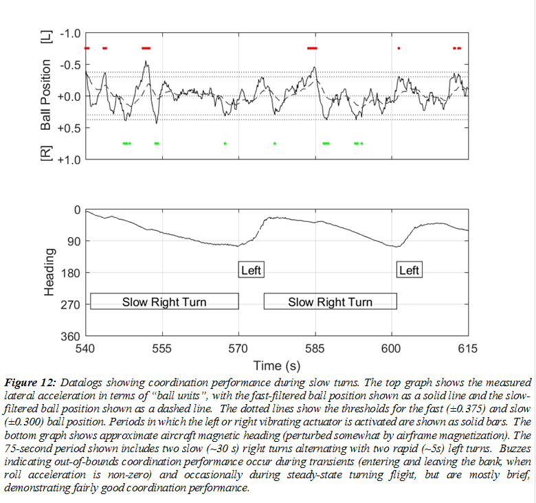
To provide “tighter bounds” for coordination during steady-state flight conditions, the lateral acceleration is smoothed a second time, using a first‑order low‑pass filter with a time constant of 2 s, and this “slow ball position” is subjected to a threshold of ±0.3, slightly tighter than the “fast ball limit” of ±0.375. This limit and the time constant can be adjusted to force the pilot to maintain better coordination during long maneuvers without making the system extremely sensitive to transient moments of uncoordination during turbulence or other rapid maneuvers. The “fast filter” always takes precedence over the “slow filter”, so there can never be a situation where the indication is in the “wrong direction”. These bounds were settled upon after extensive testing in the winter 2017-2018 timeframe and have proven satisfactory since then.
The “spin mode”, added in 2018 after a 2017 suggestion from an Innovation Prize presentation judge, has been retained, though the author has yet to test it with actual spins. When the gyro measures a yaw rate (actually a “rate of heading change”) in excess of ±90°/s, the system switches from it normal “coordination mode” into “spin mode”. Instead of providing the usual continuous buzz to indicate how to restore coordinated flight, which would be useless in this scenario, the system instead provides an intermittent/pulsed buzz (100 ms on, 100 ms off) indicating the direction of the “opposite rudder” the pilot must step on to recover from the spin. The system remains in this mode until yaw rate drops below the threshold (it may be worth considering the use of hysteresis here). Please note that this functionality has only been tested on the bench, in the aircraft with ground-based experiments with high yaw rates, and for conventional (non-inverted spins), as aircraft that has been used for flight testing is not suitable for intentional spins.
Diagnostic information is output over the serial port (so a laptop can be attached for debugging and calibration) and written to the SD card. Data-logged values include the time, CPU idle time, raw acceleration on each axis (from both sensors), filtered lateral acceleration (as used to drive the pilot feedback), heading/pitch/bank angles, rate of heading change, state of BSO055 IMU calibration, whether the system is in spin mode, and whether and why each actuator is vibrating.
Enclosure and Vibration Isolation
The control unit is contained in a Hammond RL6685 plastic enclosure, with external dimensions 200 mm L x 150 mm W x 100 mm H. The box can be hard-mounted to any solid structure in the aircraft. As vibration can interfere with accurate measurement of acceleration and small piston aircraft tend to be very high-vibration environments (vibration introduced by the engine and aerodynamic forces can cause substantial mechanical movement of poorly-damped structures in the aircraft), extensive effort has gone into mechanically reducing vibration.
The control module is attached to the enclosure using a damping mount designed for reducing vibration when using a GoPro-style camera on a small quadcopter UAV. These cost under $20 from Amazon and consist of two carbon-fiber boards separated by four rubber elastomers. The lower board is screwed to the enclosure, and the control module is attached to the upper board with a single layer of 3M 300LSE double-sided adhesive foam tape. To further reduce vibration, 4 oz of additional mass was added to the control module using sixteen 0.25 oz stick-on steel wheel weights. The wires were constrained to minimize the transmission of vibration or torque to the control module. In conjunction with the previously described software filter this has proven adequate to eliminate spurious indications, though the raw signals are still very noisy and further work in this area is warranted if improved response time or simplified mounting is desired.
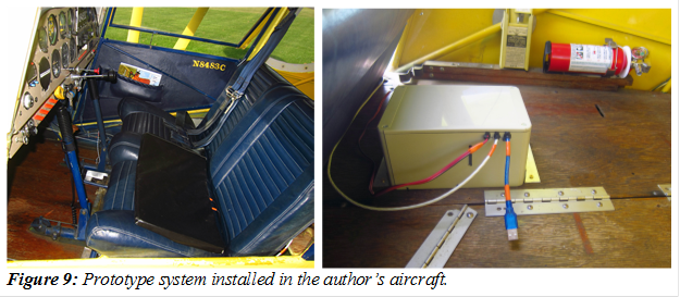
Installation
The solution was designed to be extremely easy to use and can be quickly installed either temporarily or permanently, in any aircraft, experimental or normal-category. It must simply be affixed into place and requires no integration with any aircraft systems aside from a source of 12V power (a standalone system powered by an internal battery would also be possible). A complete installation is shown in Figure 9 – the cushion on the seat and the control module mounted immediately behind the seat.
The seat cushion is merely that, a thin cushion that overlays the existing cushion. It does not need to be attached to the aircraft in any way, though it may be held in place by Velcro, double-stick tape, or permanently installed inside the seat covering if desired.
 The
control module must be attached to the aircraft in a fairly rigid manner, but it
is small and light enough to fit almost anywhere. The only constraint is that
it must be rigidly mounted to a horizontal surface, aligned with the
longitudinal axis of the aircraft, and relatively close to the aircraft’s
center of rotation to avoid unwanted sensitivity to changes in yaw rates.
The
control module must be attached to the aircraft in a fairly rigid manner, but it
is small and light enough to fit almost anywhere. The only constraint is that
it must be rigidly mounted to a horizontal surface, aligned with the
longitudinal axis of the aircraft, and relatively close to the aircraft’s
center of rotation to avoid unwanted sensitivity to changes in yaw rates.
For testing, the control module was attached to the wooden baggage deck in the test aircraft using four screws. It has remained in this location for over a year and has been removed and reinstalled several times without rezeroing, as the screwed attachment ensures a consistent alignment each time it is installed.
It could similarly be installed on the floor, under the seat, screwed to aircraft structure in an out-of-the-way location, or attached to a fuselage tube using a tube-clamp mount. Pushing it up against a bulkhead or transverse crossmember has proven sufficient to ensure accurate axis alignment, but if that was not possible, it would not be difficult to add a calibration feature that would allow arbitrary positioning (the calibration process would merely need to involve raising and lowering the tail while on the ground to distinguish between the forward/aft and left/right axes).
 There
is no limit on the length of cable between the control unit and the seat
cushion. All control signals are low voltage and low current and present very
low risk of fire, even if the wire is cut or short-circuited. The distance
between the control module and the source of power is also practically
unlimited, due to the small amount of power this device uses.
There
is no limit on the length of cable between the control unit and the seat
cushion. All control signals are low voltage and low current and present very
low risk of fire, even if the wire is cut or short-circuited. The distance
between the control module and the source of power is also practically
unlimited, due to the small amount of power this device uses.
Calibration
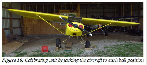
The instrument was initially calibrated with the aircraft stationary on the ground. With the aircraft parked on level ground such that the ball was centered, the lateral acceleration value is taken (using a laptop with a serial monitor), giving a zero value to compensate for the possibility that the cargo area deck is mounted unevenly relative to the airframe (though it may also include a small amount of error due to side-to-side inconsistencies in the landing gear or suspension). Then, one side of the aircraft was carefully lifted using a scissor jack under the axle stub, as shown in Figure 10, until the ball was one quarter of the way “out of its cage”. The lateral acceleration reading was recorded at this point, and then process was repeated with the ball halfway out of its cage, three quarters of the way out of its cage, and fully out of its cage (inner edge of ball exactly aligned with white cage marking). This process was then repeated while lifting the other side of the aircraft.
To get the ball fully out of its cage required lifting the wheel approximately 7 inches, for an aircraft with gear spaced approximately 70 inches apart, so the ball being “fully out of the cage” corresponds to a stationary static bank angle of 6° (I am not certain if all coordination instruments have the same scale). Figure 6 shows the aircraft jacked such that the ball is fully out to the left. Lateral acceleration at these nine ball positions (centered, four to the left, four to the right) was then entered into a spreadsheet to calculate the gain and offset for the “lateral acceleration to ball position” transfer function.
This entire initial calibration process took only about fifteen minutes, but has only been necessary once, ever. To install the system in a new aircraft, “calibration” requires only “zeroing” the measurement. This is currently done using a laptop and takes only a few minutes (either by setting an “zeroing” offset constant in the code or by using washers under the enclosure mounting screws to level it to the airframe), though it could be simplified to involve just a button push or adjustment of a zeroing screw based on feedback from a pair of indicator lights.
Open Source
A full Bill of Materials can be found in Appendix A and wiring information in Appendix B.
The full source code can be freely downloaded from our source repository at the following URL:
https://bitbucket.org/ethan_brodsky/buzzball
Test Program
 A
multi-phase test program has been conducted to verify the safety and assess the
effectiveness of this innovation. Initial testing occurred on the ground. The
initial phase of testing was conducted on the bench, using a lab power supply
for power, and “tilting” the device to simulate the forces associated with
uncoordinated flight. A second phase of testing was conducted by holding the
device at arm’s length and “spinning”, initially on foot and later in a
spinning office chair, varying the bank angle to simulate coordinated turns. The
third phase of testing, to verify electrical safety and functionality in an
in-vehicle application, the unit was installed in a car, powered by the cigarette
lighter power port the same as it would be in an aircraft, and driven around
for several hours. A modified version of the software was used to energize
both vibrating actuators at once, and these were left on for several minutes to
ensure that no hazardous overheating or other failure modes might occur. After
completing these three phases of testing, the device was deemed ready for
in-aircraft testing. It was installed as described above in the author’s
aircraft, an experimental/amateur‑built 1981 Wag‑Aero Wag‑a‑Bond Traveler,
and its functionality was tested on the ground, first with the engine off and
the aircraft lifted with a scissor jack, then taxiing the aircraft with the
engine running.
A
multi-phase test program has been conducted to verify the safety and assess the
effectiveness of this innovation. Initial testing occurred on the ground. The
initial phase of testing was conducted on the bench, using a lab power supply
for power, and “tilting” the device to simulate the forces associated with
uncoordinated flight. A second phase of testing was conducted by holding the
device at arm’s length and “spinning”, initially on foot and later in a
spinning office chair, varying the bank angle to simulate coordinated turns. The
third phase of testing, to verify electrical safety and functionality in an
in-vehicle application, the unit was installed in a car, powered by the cigarette
lighter power port the same as it would be in an aircraft, and driven around
for several hours. A modified version of the software was used to energize
both vibrating actuators at once, and these were left on for several minutes to
ensure that no hazardous overheating or other failure modes might occur. After
completing these three phases of testing, the device was deemed ready for
in-aircraft testing. It was installed as described above in the author’s
aircraft, an experimental/amateur‑built 1981 Wag‑Aero Wag‑a‑Bond Traveler,
and its functionality was tested on the ground, first with the engine off and
the aircraft lifted with a scissor jack, then taxiing the aircraft with the
engine running.
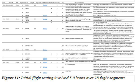
The initial phase of in-flight testing, conducted in the two months prior to Airventure 2017, consisted of 5.0 hours of testing over 18 flight segments. Each flight had written test objectives and was data-logged for later analysis. Information from these early test flights was recorded in a spreadsheet, which is shown in Figure 11.
The first 1.5 hours were used for verifying functionality of the hardware and software, testing of various vibrating actuators, and experimenting with various filtering algorithms. Major problems with barely perceptible vibrations led to a change to the GM vibrating actuators prior to the subsequent 1.6 hours of testing. Then issues with spurious indications were resolved using the previously described improvements in vibration damping hardware and software filtering over the following 1.1 hours. With those issues resolved, the final 0.8 hours were used to experiment with various thresholds.
The second phase of in-flight testing ran from Jan-May 2018 and involved 33.0 hours of flight time over 23 separate days of flying (as of May 15), with multiple different pilots flying. This was intended to assess the impact of the system in real‑world flying conditions. The system was operational for nearly every flight conducted in my aircraft over a period of five months.
In its current incarnation, the system has been installed in the author’s aircraft for the last twelve months (June 2018 to June 2019), for many flights with several different pilots and roughly 110 hours of additional use. All in all, the system has flown for roughly 146.5 hours and has been in active use for the majority of that time.
Results
The system operates as expected. The system has operated flawlessly for over a year, with the only change being to revert the software to using the signal from the LSM303-based acceleration sensor for pilot feedback and to use the measurements from the BNO055 only for datalogging.
Figure 12 shows data from the system in operation during some well-coordinated turns, with only brief buzzes indicating coordination briefly going out-of-bounds during transients (entering and leaving the bank, when roll acceleration is non-zero) and occasionally during steady-state turning flight.
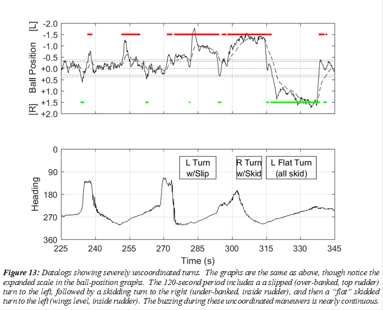
Figure 13 shows data from the system in operation during severely uncoordinated flight – a slipped (over-banked, top rudder) turn to the left, followed by a skidding turn to the right (under-banked, inside rudder), and a “flat” skidded turn to the left (wings level, inside rudder). The buzzing during these maneuvers is continuous and seemingly impossible to ignore (though it would be interesting to study whether it might still be missed during periods of stress or distraction).
Cost
This solution was intended to and has proved to be extremely affordable. The actual cost to build this prototype was approximately $250, and a duplicate could easily be constructed by a third party for that price.
 All
software was developed using free tools, though it does require a personal
computer to program the module. Efforts were made this year to use exclusively
commercially-available off-the-shelf components, simplifying the task for
anyone who would like to build their own.
All
software was developed using free tools, though it does require a personal
computer to program the module. Efforts were made this year to use exclusively
commercially-available off-the-shelf components, simplifying the task for
anyone who would like to build their own.
The only tools required are basic supplies for splicing, crimping, and heat-shrinking of wire. Installation cost should be near zero, and it should be very easy to move between aircraft.
Discussion and Future Study
While we have so far only undertaken limited testing of this system, it offers the potential for very in-depth analysis of a pilot’s coordination performance. Unfortunately, most of the ideas proposed for study in 2018 have yet to be tried, so most of this section is identical to what was submitted last year. The only new idea proposed is to try the Pololu AltIMU-10 v4 sensor, which integrates a newer version of the LSM303 sensor with a gyro and digital barometer, giving the same “nine-axis” sensing that the BNO055-based solution did, plus the ability to sense pressure altitude.
The following ideas were all proposed last year but have not been tried. As the computer in the control module is capable of measuring and logging lateral acceleration without triggering the seat vibrators, it is possible to compare a pilot’s coordination with and without tactile feedback. After each flight, a report could be generated showing what percentage of time the ball was within certain tolerances of center. We hypothesize that the percentage of time spent in coordinated flight will
 |
be improved with the tactile feedback. It would also be interesting to break down the report into sub-categories such as “coordination performance in straight and level flight”, “coordination performance while climbing” (with positive deck angle), and “while rolling left or right”. As the IMU also measures heading, coordination performance “while in a stable standard rate left turn”, “while in a steep turn”, etc… could also be evaluated. Replacing the six-axis IMU with a nine-axis unit (as discussed in the “Further Study” section last year) has allowed this data to be collected, but detailed analysis still has not been performed.
There are a number of interesting research questions relating to the use of this system. It seems likely that coordination performance is improved when the system is installed, but it is uncertain whether flying with the system may eventually help train the pilot to have a “feel” for coordinated flight that leads to lasting gains in coordination performance that would persist when flying in an aircraft without the system installed, or whether the tactile feedback acts as a “crutch” that impedes development of “natural” or “seat-of-the-pants” perception of coordination.
The author has anecdotally observed that his performance in maintaining coordination has substantially improved over several years of using this system and that those improvements persist in other aircraft or when the system is disabled, but it is impossible to ascertain whether that is due to the system itself or just a normal progression of flying skill.
A more philosophical question is whether systems like this should be thought of as “training tools” or “warning systems”, and what the design implications are for either of those choices. If it is to be a “training tool”, then it can be programmed to have extremely low thresholds for providing feedback. This may “teach” the pilot to be extremely cognizant of coordination, and I have experimented with this and found that it is effective in leading to very precise rudder use after only a few hours of flying. However, after a few hours of flying like this, the buzz may lose its “urgency” – it is just one more bit of feedback that a pilot learns to unconsciously responds to while flying. This makes the system much less valuable as a “warning system”, as warnings quickly lose their effectiveness of they frequently go off during non-hazardous conditions. Alerts intended to warn a pilot of an unanticipated dangerous situation must break through the distraction, mental clutter, and tunnel vision associated with stressful, task-saturated, or other challenging periods of flight, because those are the times when a pilot is more likely to neglect to pay attention to aircraft handling. This suggests that the system should instead have higher thresholds for actuation, vibrating only when coordination is so far out as to create a hazard, so as to avoid “desensitizing” the pilot to its warning.
So far, the pilot’s personal experience after several years of flying with this is that “desensitization” is not an issue – on the contrary, as performance improves and the buzzes become less and less frequent, they become more shocking when they happen unexpectedly, to the point where I will find myself verbally apologizing (to myself?) when they happen.
As the only pilots who have tested this system so far are the author and a small number of friends, I hope to someday loan it to a number of pilots of varying experience levels flying a variety of airplanes and record and assess their performance over time, with the hope that it will improve the coordination performance in all cases. Finally, it would be interesting to measure the performance of the system in VFR conditions with the lower half of the conventional turn coordinator instrument covered to remove visual feedback, forcing the pilot to rely only on tactile indication, and study how dependency on the turn coordinator instrument varies with flight experience for various types of pilots.
Some thought was given to varying the power level of the vibrating indicators or pulsing them periodically for various degrees of out-of-coordinated flight, but it was found that the buttocks are not particularly sensitive to slight variations in tactile simulation, so an all-or-nothing indication was chosen (A pulsed indication was used for spin mode to distinguish it from the steady-state indication used for simple out-of-coordinated flight and this has proven to be noticeable).
It may be advantageous for the tactile stimulation to be more intense or to occur in a more sensitive area of the body, but the non-invasive simplicity of mounting the actuators in the seat led to this choice. Other options have been discussed, including auditory feedback using stereo tones over the headset, “heads-up” visual indicators in the panel, vibrating stimulation on the hands or other more sensitive parts of the body, as well as the possibility that such feedback could be used for other indications like course guidance during cross-country or instrument flight.
The original concept for this invention, conceived during a long flight accompanying a friend ferrying a Luscombe from Oregon to Wisconsin, was that the system would shock the pilot “in a sensitive area” to “punish” them for not maintaining coordinated flight, but for this initial proof of concept, we have opted for a less punitive means of training. The idea of using a third indicating element to “reward” the pilot with positive reinforcement for maintaining coordinated flight have also been discussed, but not implemented.
Technical Notes
This section includes a number of technical notes which did not fit elsewhere.
It is important that IMU be mounted close to the aircraft’s center of gravity. All testing was performed with the unit mounted approximately two feet behind the test aircraft’s CG. A mounting location far from the CG means that angular acceleration (changes in yaw rate) will create lateral acceleration at that measurement location, with the direction depending on their position relative to the yaw center. Liquid-filled turn coordinators installed far from an aircraft’s CG are also subject to similar perturbations. This is unlikely to be a factor in most small general aviation aircraft, where distances from the CG are likely to be small, but one should note that it would be undesirable to put the sensing unit in the tail. Mounting locations away from the aircraft centerline laterally might also cause small measurement errors. This is likely to be negligible in small GA aircraft, but mounting the sensor at the end of the wing would also be undesirable.
One should also note that magnetometer readings are unreliable in aircraft that have magnetized airframes. This is a common problem in aircraft with rag-and-tube welded fuselages and has proven to be a major issue in my aircraft. This leads to somewhat incorrect heading readings which do not affect the operation of the unit (spin mode is based on yaw rates measured with the gyros, not the magnetometer), but complicates the analysis of datalogs. It was hoped that the switch to the nine-axis IMU with its built-in gyros would alleviate this situation, but erroneous heading information in the datalogs has still been an issue – no amount of yaw rate information can yield a correct absolute heading indication without some reliable earth-based reference.
The BNO055 chipset used in the IMU is capable of providing absolute orientation with either Euler Angles or Unit Quaternion. The manufacturer cautions that the Euler angle mode may lead to incorrect measurements of pitch and roll at steep (>45°) angles. As these values are used only for datalogging and not part of the feedback control algorithm, we have opted to continue using this representation for convenience, rather than switching to Unit Quaternion mode and doing the calculations ourselves.
A design decision had to be made whether the unit should “normalize” its out-of-coordination quantification based on load factor. The physical inclinometer in the turn coordinator (a segment of a circular arc) will exhibit reduced sensitivity to a given lateral acceleration at higher load factors, as it is measuring the direction of the net acceleration vector projected onto the plane of the instrument panel. To be representative of that, the software would have to normalize lateral acceleration based on the net acceleration vector (ignoring any longitudinal component).
We have opted not to do that, which means that the sensitivity of the instrument to out-of-coordinated conditions will be greater at high load factors. If the vibrations start at “half a ball out” at 1 G, it will vibrate at “a quarter ball out” at 2 G. Whether this is the right choice or not is open to question, but my intuitive take on this is that coordination becomes especially crucial in highly loaded flight, so increased sensitivity here is appropriate. If someone feels otherwise, it would be easy to normalize by dividing ay by √(ay2 + az2) or using tan-1(ay/aZ) before further processing. One should note that the normalization and coordination situation becomes complicated when the aircraft is inverted, and this device has not been tested in that situation.
Summary and Conclusions
This innovation is a development in a new concept in providing bilateral tactile feedback to help improve pilots’ coordination performance. It has proven effective over many hours of testing in the author’s aircraft and appears to satisfy its intended function, helping the pilot maintain awareness of aircraft coordination without having to look at an instrument. It could easily be combined with other pilot aids such as stick shakers, heads-up displays, augmented reality, or other systems for improving pilot feedback.
The concept could easily be integrated into any “glass panel” or other electronic instrument that senses lateral acceleration (any instrument that displays a “ball” indication does) and has two unused channels of 12V drivers. The cost to implement this would basically just be that of the vibrating actuators and wiring, as the software required to implement this functionality is trivial.
The innovation was well-received at
AirVenture 2017 (finishing fourth), was substantially improved in 2018
(although it was not selected as a finalist), and minor improvements and a
great deal of additional testing have been conducted since that submission. The
author intends to continue experimenting between now and Oshkosh (and after) and
invites any EAA members to build their own and test out or improve upon this
concept. Seriously, if anyone is interested and has read this far, email me
and I’ll help you build one!
Appendix A: Bill of Materials
Current Embodiment (as of 2018-07-01)
|
Qty |
Part |
Vendor |
Price |
|
1 |
Arduino Mega 2560 R3 (w/USB cable) (A000067) |
Amazon |
$43.42 |
|
1 |
Arduino 9-Axes Sensor Shield (A000070) |
Amazon |
$20.12 |
|
1/3 |
Gikfun Prototype Shield DIY KIT for Arduino UNO R3 328P Ek1038 (pkg 3) |
Amazon |
$11.58 |
|
1 |
Adafruit 1120 Sensor Development Tools Triple-axis Board - LSM303 |
Amazon |
$17.49 |
|
1 |
Adafruit Motor/Stepper/Servo Shield for Arduino v2.3 kit |
Amazon |
$21.99 |
|
1 |
Adafruit Assembled Data-Logging Shield for Arduino |
Amazon |
$16.16 |
|
2 |
General Motors 84017512 Haptic Seat Motor |
GM dealer |
$82.70 |
|
1 |
GoolRC Gimbal FPV Camera Mount with Anti Vibration Plate for DJI |
Amazon |
$16.99 |
|
1 |
DROK 90010 Waterproof DC Buck Converter 8-22V to 1-15V 3A |
Amazon |
$9.96 |
|
1/10 |
iMBA-CCTV-PGTM Security Camera Power Plug Pigtail Cable (pkg 10) |
Amazon |
$5.49 |
|
1 |
RoadPro Fused Cigarette Lighter Plug with leads |
Amazon |
$3.88 |
|
1 |
Hammond RL66865 plastic enclosure |
Mouser |
$12.53 |
|
1 |
Fiskars 11x18x0.75” foam knee cushion |
Home Depot |
$5.97 |
|
½ yd² |
Marine vinyl (black) |
Jo-Ann Fabric |
$4.50 |
|
~5 ft |
M27500/22ML4T23 multiconductor cable |
Stock |
|
|
~5 ft |
Two-conductor power cable (18 AWG) |
Stock |
|
|
4 |
Crimp bootlace ferrule (yellow, suitable for 22 AWG wire) |
Stock |
|
|
6 |
3M TMW adhesive-lined polyolefin heat-shrink (.183 and .255) |
Stock |
|
|
16 |
0.25 oz stick-on steel wheel weights |
Stock |
|
|
|
3M 300LSE double-stick tape |
Stock |
|
|
3 |
Rubber Grommets |
Stock |
|
|
10 in |
1x1 x 1/16 aluminum angle |
Stock |
|
|
4 |
Blind rivets (Al, 1/8” diameter, 1/4” grip length) |
Stock |
|
|
8 |
Brass wood screws |
Stock |
|
|
1 |
Shield Stacking Header Set for Arduino Uno R3 |
Stock |
|
|
1 |
4 GB SD card (for datalogger) |
Stock |
|
|
1 |
CR1220 coin cell battery (for datalogger) |
Stock |
|
|
|
Crimp splices |
Stock |
|
|
Total |
$260.62 |
||
Appendix B: Wiring
Motor wiring:
L+ White
L˗ White/Blue
R+ White/Orange
R˗ White/Green
Pinout on motor driver board:
L M3 (+ outer, ˗ inner)
R M4 (+ outer, ˗ inner)
Adafruit 1120/LSM303DLHC to Arduino header on midboard:
3V3 n/c
Vin 5V Red
GND Gnd Black
DRDY n/c
I1 n/c
I2 n/c
SDA SDA Blue
Power supply module:
Black: Input negative, Arduino DC jack negative, Motor driver negative
Red: Input positive, Motor driver positive
Yellow: Arduino DC jack negative
Appendix C: I2C Address Assignments
0x19 LSM303DHLC Linear Acceleration Sensor on Adafruit 1120
0x1E LSM303DHLC Magnetic Field Sensor on Adafruit 1120
0x28 BNO055 Absolute Orientation Sensor in Arduino A00700070 Nine-axis IMU Shield
0x60 Adafruit 1438 Motor/Stepper/Servo Driver Shield (jumper configurable 0x60-0x80)
0x68 PCF8523 Real-time clock in Adafruit 1141 SD datalogging shield